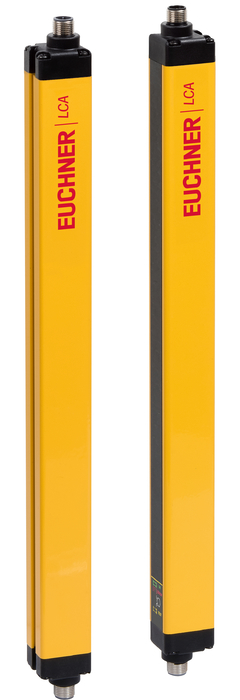

Protective function
finger protection
Cascading (series connection)
Following combinations are possible:
| Variante A: | Master-slave 2-slave 1 |
| Variante B: | Master-slave 1 |
LED function display
Transmitter
Receiver
| LED OK | Normal operation |
| LED ERROR | Faults |
| LED STOP | Stop |
| LED TEST | Test function |
| LED START | Start/ restart |
| LED SIGNAL LOW | Weak signal |
Connector assignment transmitter / receiver
| Plug connector (view of connection side) | Pin | Designation | Function | Conductor coloring of connection cable |
|---|---|---|---|---|
| 1 | 24 V DCB | Operating voltage, 24 V DC | BN | |
| 2 | LINE_A | Communication MASTER-SLAVE | WH | |
| 3 | 0 V DC | Operating voltage, 0 V DC | BU | |
| 4 | LINE_B | Communication MASTER-SLAVE | BK | |
| 5 | FE | Function earth (must be connected to meet the EMC requirements) | GY |
| Resolution | 14 mm |
| Height of the protective field | 910 mm |
| Height of the sensor | 963 mm |
| Maximum length of connecting cables | 100 m |
| Range of the protective field | 6000 mm |
| Dimensions | 28×30 mm |
| Ambient temperature | -20 … 55 °C |
| Degree of protection | IP 65 / IP 67 |
| Installation orientation | Any |
| Connection | Plug connector M12 (5-pin transmitter / 8-pin receiver) |
Electrical connection ratings
| Cascadable | Yes |
| Muting possible | In combination with external sensors and an evaluation unit |
| Operating voltage DC | 24 V DC -20% … +20% |
| Current consumption | 400 mA |
| Power consumption | |
| Transmitter | 1 W |
| Receiver | 2 W |
| LED indicator | Yes |
Reliability values according to EN ISO 13849-1
| ESPE type | 4 |
| Performance Level | PL e |
| PFHD | 1,78×10⁻⁸ |
| Safety Integrity Level | SIL 3 / SILCL 3 |
| Mission time | 20 y |