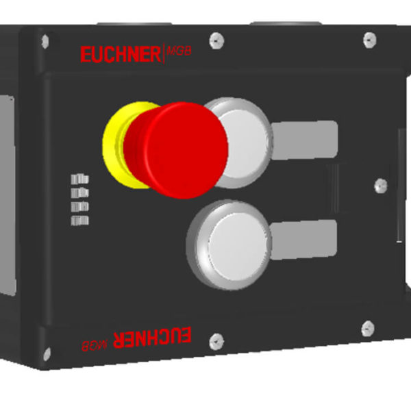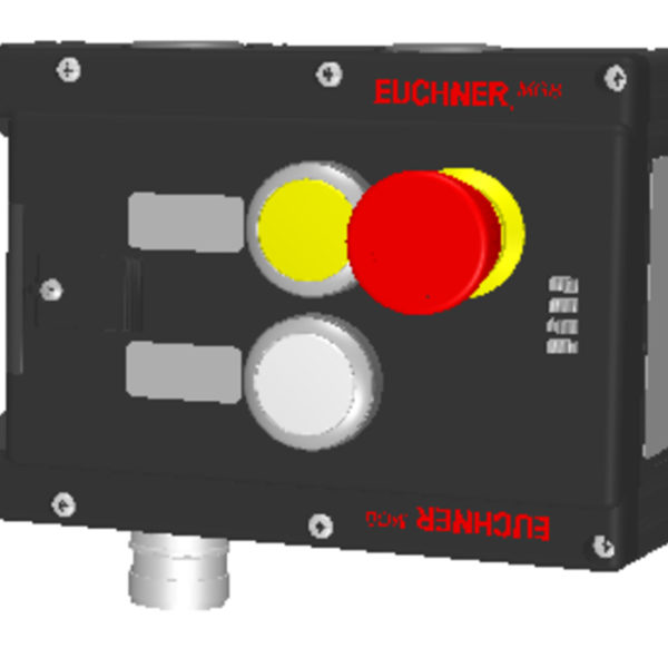
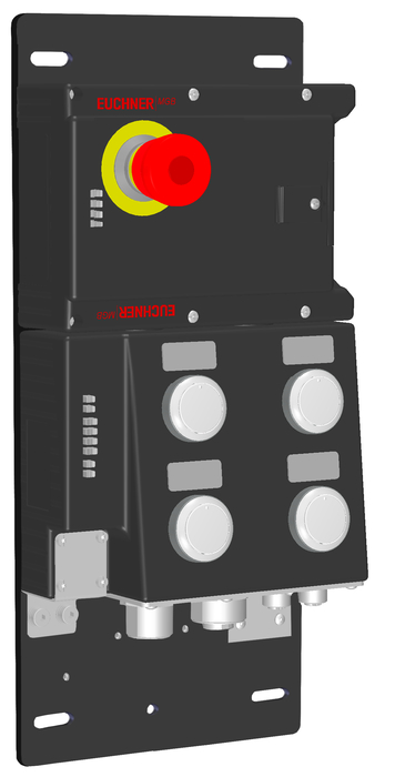
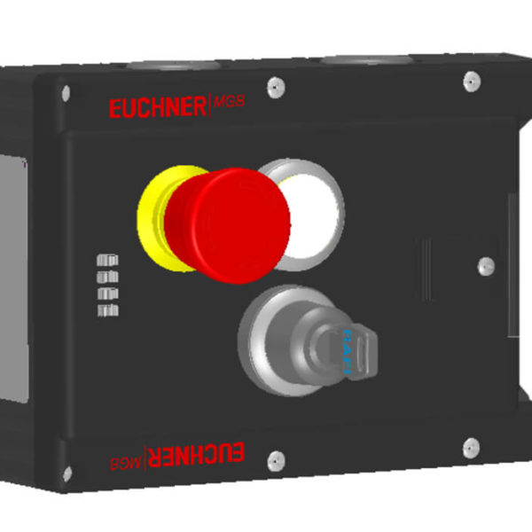
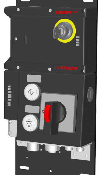
Dimension drawing
Wiring diagram
MGB: The MGB-System in use
MGB: MGB Impact test
MGB: Mounting left door, with escape release
Mounting left door, without escape release
Mounting right door, without escape release
MGB: Deactivating guard lock monitor
MGB: Activating guard lock monitor
MGB: Activating release monitoring
MGB: Change color-lens push button
Dimension drawingWiring diagram
Technical dataApprovals
Mechanical values and environment
| Housing material | Reinforced plastic, die-cast zinc nickel-plated, stainless steel |
| Weight | |
| Net | 3,1 kg |
| Ambient temperature | |
| At UB = 24V DC | -20 … 55 °C |
| Degree of protection | IP54 |
| Resilience to vibration | In accordance with EN 60947-5-3 |
| Mechanical life | 1 x 10⁶ |
| In case of use as door stop, and 1 Joule impact energy | 0,1 x 10⁶ |
| Installation orientation | Door hinge DIN right |
| Reaction time | |
| Guard locking | max.250 ms Switch-off time |
| Emergency stop / machine stop | max.100 ms Switch-off time |
| Door position | max.250 ms Switch-off time |
| Bolt position | max.250 ms Switch-off time |
| Switching frequency | 0,25 Hz |
| Connection | |
| M12 Power, A-coded | |
| M12 Power, A-coded | |
| Ethernet/IP cable, Cat. 5e min. | M12 D-coded, screened |
| M12 D-coded, screened | |
| Guard locking principle | Closed-circuit current principle |
| Locking force FZh | 2000 N |
Electrical connection ratings
| Current consumption | max.500 mA |
| Rated insulation voltage Ui | 75 V |
| Rated impulse withstand voltage Uimp | 0,5 kV |
| Maximum feed-in current in the connection block | |
| X1, X2 | max.4000 mA |
| EMC protection requirements | In accordance with EN 61000-4 and EN 61326-3-1 |
| Degree of contamination (external, according to EN 60947-1) | 3 |
| Connecting cable | |
| Ethernet | Ethernet/IP cable, Cat. 5e min. |
| Safety class | III |
| Transponder coding | Unicode |
| Power supply X1 | |
| Operating voltage DC | |
| L1 | 24 V DC -15% … 10% |
| Auxiliary voltage DC | |
| L2 | 24 V DC -15% … +10% |
| Fusing | |
| external | min.1 A Slow blow |
| Power supply X2 | |
| Operating voltage DC | |
| L1 | 24 V DC -15% … 10% |
| Auxiliary voltage DC | |
| L2 | 24 V DC -15% … +10% |
Work area
| Assured switch-off distance Sar | max.65 mm |
Interface, bus
| Data interface | |
| Data protocol | |
| Bus protocol | Ethernet/IP |
| Safety protocol | CIP Safety |
Controls and indicators
| Belegungsschema | B1 |
| Belegungsschema | L1 |
| Position 1 | |
| Ausfuhrung | Emergency stop illuminated |
| Einlegeschild | |
| Extras | With adhesive ring |
| Farbe | |
| Schaltelement | 2 pos. driven NC |
| Position 90 | |
| Ausfuhrung | Illuminated push buttons |
| Einlegeschild | |
| Extras | |
| Farbe | |
| Schaltelement | 1NO |
| Position 92 | |
| Ausfuhrung | Illuminated push buttons |
| Einlegeschild | |
| Extras | |
| Farbe | |
| Schaltelement | 1NO |
| Position 93 | |
| Ausfuhrung | Illuminated push buttons |
| Einlegeschild | |
| Extras | |
| Farbe | |
| Schaltelement | 1NO |
| Position 95 | |
| Ausfuhrung | Illuminated push buttons |
| Einlegeschild | |
| Extras | |
| Farbe | |
| Schaltelement | 1NO |
Other
| Additional feature | Incl. cover set ID. No. 120344 |
| Product version number | V1.2 |
| Slide-in label | 4 pcs. without marking |
Reliability values according to EN ISO 13849-1
| Monitoring of guard locking and the safety guard position | |
| Category | 4 |
| Performance Level | PL e |
| PFHD | 3.37 x 10⁻⁹ |
| Diagnostic Coverage (DC) | 99 |
| Control of the guard locking | |
| Category | 4 |
| Performance Level | PL e |
| PFHD | 4.91 x 10⁻⁹ |
| Emergency stop | |
| B10D | |
| Emergency stop | 0.1 x 10⁶ |
| Emergency-stop evaluation | |
| Category | 4 |
| Performance Level | PL e |
| PFHD | 3.05 x 10⁻⁹ |
| Safety Integrity Level | SIL 3 (EN 62061:2005) |
| Mission time | 20 |