
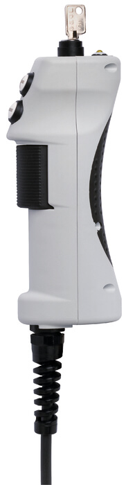
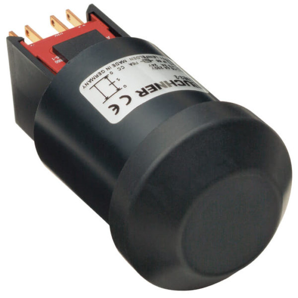
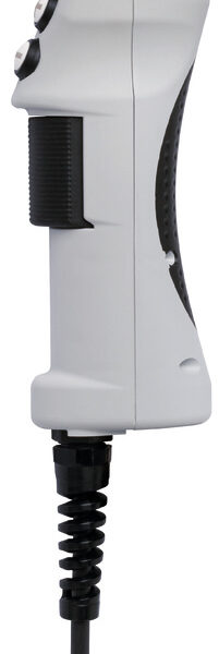
3-stage functionEnabling function is active only in the second stage (middle position, actuating point). If the pushbutton is released or pushed further (panic function), the enabling is removed (dependent on the wiring, see function sequence).
LED indicatorThe LED indicator is used for visual feedback directly at the enabling switch.
+ and – buttonsThese buttons can be cond individually. For example for moving axes in the positive or negative direction.
Key-operated rotary switchFor individual use, e.g. as operating mode selector switch.
CableThe high-quality connection cables are available in a coiled version.
Dimension drawing
Dimension drawing
Wiring diagram
Wiring diagram
Wiring diagram
Dimension drawingDimension drawingWiring diagramWiring diagramWiring diagram
Technical dataApprovals
Mechanical values and environment
| Material | PA, CR, TPE |
| Weight | |
| Net | 2 kg |
| Ambient temperature | -5 … 60 °C |
| Degree of protection | IP54 |
| Mechanical life | 1 x 10⁶ |
| Switching principle | Snap-action contact element |
| Number of changeover contacts | 3 |
| Connection | Plug connector number of pins 12 |
| Cable length | |
| coiled | 3,5 m |
Electrical connection ratings
| Rated conditional short-circuit current | 100 A |
| Utilization category according to EN 60947-5-1 | |
| DC-13 | 24V 1A |
| 24V 0.3A | |
| 24V 0.01A | |
| Short circuit protection according to IEC 60269-1 | 2A gG |
| Rated insulation voltage Ui | 250 V |
| Rated impulse withstand voltage Uimp | 1,5 kV |
| Degree of contamination (external, according to EN 60947-1) | 3 |
| Connecting cable | 12×0.14mm? |
| Switching characteristics | 3-stage enabling switch |
Other
| Additional feature | |
| Key-operated switch | 1 |
| Pushbutton + | 1 |
| Pushbutton — | 1 |
| LED yellow | 1 |
| In compliance with | 60947-5-8 |
Reliability values according to EN ISO 13849-1
| Enabling switch | |
| B10D | 0,1 x 10⁶ |


