


Short circuit monitoring
The switch generates its own clock signal on the output cables OA/OB.
Pay attention to this aspect when connecting to control systems and relays.
Multicode evaluation
Every suitable actuator is detected by the switch.
Category according to EN 13849-1
Due to two redundantly designed semiconductor outputs (safety outputs) with internal monitoring suitable for:
- Category 4/PL e according to EN 13849-1
Important: To achieve the stated category in accordance with EN ISO 13849-1, both safety outputs (OA and OB) must be evaluated.
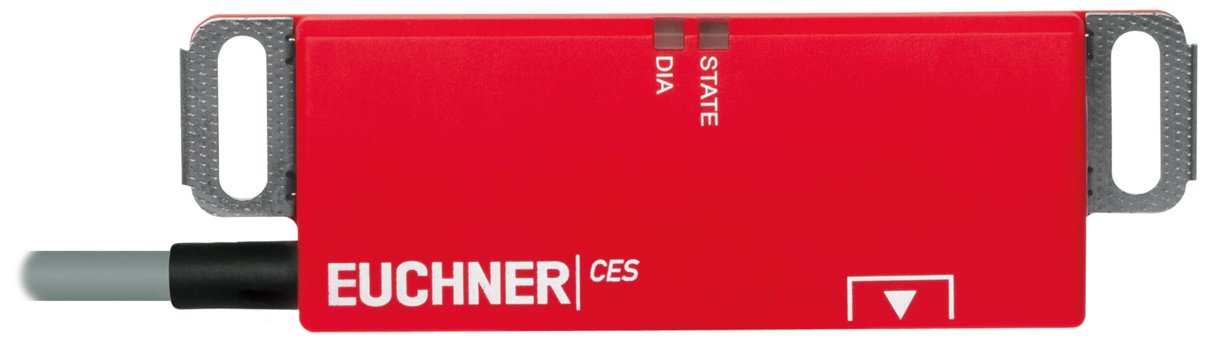
LED indicator
| STATE | Status LED |
| DIA | Diagnostics LED |
Additional connection
| OUT | Monitoring output (semiconductor) |
Approach directions
Typical operating distance
(Actuator CES-A-BLN… in conjunction with safety switch CES-AP-C.2-… in case of mounting on plastic)
For a side approach direction for the actuator and safety switch, a minimum distance of s = 6 mm must be maintained so that the operating distance of the side lobes is not entered.
Attention:
The operating distance may vary depending on the background material and installation situation.
Terminal assignment
| Designation | Function | Conductor coloring of connection cable |
|---|---|---|
| UB | Power supply, DC 24 V | BN |
| FO1A | Safety output, channel 1 | WH |
| 0V | Ground, DC 0 V | BU |
| FO1B | Safety output, channel 2 | BK |
| OUT | Monitoring output | GY |
| — | n.c. | PK |
| Housing material | Plastic, PBT |
| Weight | |
| Net | 0,22 kg |
| Ambient temperature | |
| Cable dynamic | 0 … 65 °C |
| Cable static | -40 … 65 °C |
| Degree of protection | IP67, IP69K |
| Resilience to vibration | In acc. with EN IEC 60947-5-2 |
| Mounting method | Surface mounting on metal |
| Mounting distance | |
| Between 2 switches or 2 actuators | min.400 mm |
| Installation orientation | Any |
| Tightening torque | |
| Fixing screws | max.1 Nm |
| Ready delay | 0,5 s |
| Switching frequency | max.1 Hz |
| Connection | connection cable PVC, length 5m |
| Bending radius | |
| static | 5 x cable diameter |
| Dynamic | 10 x cable diameter |
Electrical connection ratings
| Operating voltage DC | |
| UB | 24 V DC 15% … 15% Regulated, residual ripple < 5 % |
| Current consumption | max.30 mA |
| Utilization category according to EN 60947-5-2 | |
| DC-13 | 24V 150mA |
| Fusing | |
| External (operating voltage) | 0,25 … 8 A |
| Rated insulation voltage Ui | 75 V |
| Rated impulse withstand voltage Uimp | max.1,5 kV |
| EMC protection requirements | In acc. with EN IEC 60947-5-3 |
| Degree of contamination (external, according to EN 60947-1) | 3 |
| Switch-on time | |
| Safety outputs | max.300 ms |
| Safety class | III |
| Risk time according to EN 60947-5-3 | max.260 ms |
| Monitoring output OUT | |
| Type of output | p-switching, short circuit-proof |
| Switching current | max.50 mA |
| Output voltage | 0,8 x UB … UB V DC |
| Safety outputs OA/OB | |
| Test pulses | max.0,3 ms |
| Test-pulse interval | min.100 ms |
| Type of output | Semiconductor outputs, p-switching, short circuit-proof |
| Switching current | |
| per safety output | 1 … 150 mA |
| Output voltage | |
| HIGH U(OA) / U(OB) | UB-1,5V … UB V DC |
| LOW U(OA) / U(OB) | 0 … 1 V DC |
| Rated conditional short-circuit current | 100 A |
| Off-state current Ir | max.0,25 mA |
| Discrepancy time | max.10 ms |
Work area
| Repeat accuracy R | ? 10 |
Other
| For the approval according to UL the following applies | Operation only with UL class 2 power supply, or equivalent measures |
Reliability values according to EN ISO 13849-1
| Monitoring of the safety guard position | |
| Category | 4 |
| Performance Level | PL e |
| PFHD | 1.8 x 10⁻⁹ |
| Mission time | 20 |
In combination with Actuator CES-A-BLN-R2-100776, CES-A-BLN-U2-103450, CES-A-BLN-L2-104510, CES-A-BLN-U2-112710Operating distance
| Switch-on distance | 15 mm |
| Assured switch-off distance Sar | |
| In x/z direction | max.40 mm |
| In y direction | max.60 mm |
| Assured operating distance Sao | min.10 mm |
| Switching hysteresis | min.1 mm |
In combination with Actuator CES-A-BDN-06-104730Operating distance
| Switch-on distance | 19 mm |
| Assured switch-off distance Sar | |
| In x/z direction | max.40 mm |
| In y direction | max.60 mm |
| Assured operating distance Sao | min.14 mm |
| Switching hysteresis | min.1 mm |


