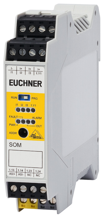

OSSDs (Output Signal Switching Devices)The OSSD is of redundant design according to category 4 EN ISO 13849-1. Safety-related control is via the bus by a suitable monitor, for example by a GMOx or SMOx. Operational switching is also possible directly by the control system with appropriate parameter settings.
Inputs and outputsA feedback loop can be connected directly to the SOM. Depending on the parameter settings, further inputs and outputs can also be used.
LED function display
| PWR | Green, AS-Interface power |
| ASi | Red, bus communication |
| OUT | Yellow, state of output signal switching device |
| ALARM | Red, can be set as required by control system |
| I1…I3 | State of the corresponding input |
| 1.Y1 | State of the input |
Dimension drawing
Wiring diagram
Dimension drawingWiring diagram
Technical dataApprovals
Mechanical values and environment
| Housing material | Polyamide PA 6.6 |
| Ambient temperature | 0 … 55 °C |
| Degree of protection | IP20 |
| Mounting method | Mounting rail 35mm according to DIN EN 60715 TH35 |
| Reaction time | |
| Safety circuit off | max.50 ms |
| Connection | Connection terminals |
| E1 terminal I1, E2 terminal I2, E3 terminal I3 | |
| Number of inputs | 3 |
| Output contact set 1: 1.13, 1.14; output contact set 2: 1.23, 1.24 | |
| Number of safety contacts | 1 |
| Terminal 1.Y1, I+ | |
| Number of inputs | 1 |
Electrical connection ratings
| ASi voltage | |
| DC | 30 V |
| ASi operating current | max.200 mA |
| Current | 0,1 A Supply for sensors |
| LED indicator | |
| 3 LEDs yellow (I1, I2, I3) state of input E1, E2 and E3 | |
| 1 x LED yellow (1. Y1) state EDM input 1.Y1 | |
| LED green (Pwr) AS-i power supply | |
| LED red (Fault) AS-i fault | |
| LED yellow (Out) relay has switched and error message | |
| LED red (Alarm) PLC is signaling alarm | |
| Rated insulation voltage Ui | 6000 V |
| Overvoltage category according to IEC EN 60664-1 | 3 |
| Connecting cable | 9W |
| Max. contact load | |
| DC -13 | 3A 24V |
| AC -15 | 3A 250V |
| Terminal 1.Y1, I+ | |
| Type of input | Feedback loop (EDM) |
| Current via feedback loop | |
| at 24V DC | 10 mA From AS-i (EDM) |
| Output contact set 1: 1.13, 1.14; output contact set 2: 1.23, 1.24 | |
| Type of output | |
| 2 NO contacts per safety output | Relay contacts, floating, positively driven (redundant) |
| E1 terminal I1, E2 terminal I2, E3 terminal I3 | |
| Type of input | standard |
Interface, bus
| Data interface | Address programming socket AS-i (ADDR) |
Controls and indicators
| Control/indicator | |
| Ausfuhrung | |
| Einlegeschild | |
| Extras | |
| Farbe | |
| Schaltelement |
Other
| In compliance with | EN 61 508, EN 62 061, EN ISO 13 849-1 |
Reliability values according to EN ISO 13849-1
| Performance Level | PL e |
| Category | 4 |
| PFHD | 3.3 x 10⁻⁹ |
| SIL CL | 3 |
| Mission time | 20 y |