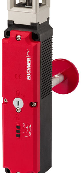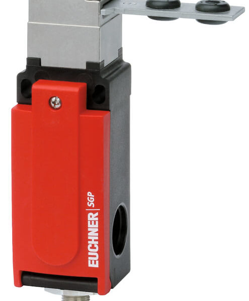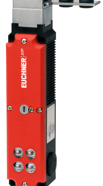


Switching directionRight, left or both sides.
AS-Interface inputs
| D0, D1 | Positively driven NC contact 1 |
| D2, D3 | Positively driven NC contact 2 |
Evaluation is performed via a safety monitor.
AS-Interface outputs
| D1 | Red LED |
| D2 | Green LED |
LED function display
- The Power LED indicates the operating voltage on the bus.
- The Fault LED indicates if a fault has been detected on the AS-Interface bus.
- The green and the red LEDs can be controlled as required by the control system via the bus using bits D1 and D2.
Dimension drawing
| Housing material | Anodized die-cast alloy |
| Weight | |
| Net | 0,3 kg |
| Ambient temperature | -25 … 70 °C |
| Degree of protection | IP67 |
| Mechanical life | 30 x 106 |
| Contact material | Silver alloy, gold flashed |
| Switching principle | Slow-action switching contact |
| Installation orientation | Any |
| Number of door position positively driven contacts | |
| According to ASI Safety at work | 2 D0, D1 / D2, D3 |
| Connection | |
| 1 x | Plug connector M12 |
| Approach speed | |
| max. | 0,1 … 60 m/min |
| Actuating element | |
| Plain bearing metal | Lever arm |
| Actuating force | min.15 N |
Electrical connection ratings
| ASi voltage | 30 V 22,5 … 31,6 V |
| ASi operating current | max.45 mA |
| ASi slave type | |
| According to ASI specification 2.1 | ID code B |
| EA code 7 | |
| ASi data in | |
| According to ASI Safety at work | D0, D1 / D2, D3 |
| ASi data out | |
| LED red | D1 |
| LED green | D2 |
| ASi LED | |
| LED green | Power |
| LED red | Fault |
Reliability values according to EN ISO 13849-1
| B10D | 20 x 106 |